LLM Handles Intent, Code Handles Geometry
Why CubeMuse uses a JSON instruction set instead of raw coordinates, splitting what to build from how to draw it.
You want AI to build a Minecraft castle. The most direct approach is to have the model output coordinates and materials, block by block.
A 30×30×30 building has roughly 27,000 voxel positions. Even listing only non-empty blocks, the output is thousands of lines of coordinates plus materials, each looking like this:
[12, 5, 8, "stone_bricks"]Token cost is a problem, but only on the surface. The deeper problem is that a pile of coordinates is not editable, not composable, cannot be incrementally modified, and does not transfer across formats. When the user says “make the roof red,” there is no “roof” in a coordinate list. There are only blocks that happen to form one.
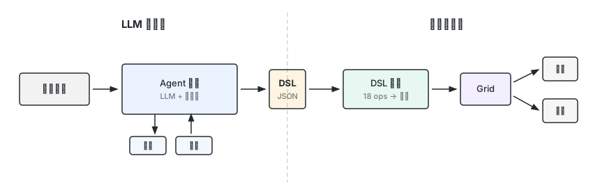
CubeMuse’s approach is to hand “what to build” to the LLM and “how to draw it” to a deterministic engine. The two systems communicate through a JSON instruction set. This article explains how that separation works and why it is designed this way.
What CubeMuse Is#
CubeMuse is a browser-based AI building generator for Minecraft players and creators. The user describes a building in natural language, the AI produces a structured build plan, a deterministic engine renders the plan into a voxel structure, and the result is exported as a Java Edition file (.litematic) or Bedrock Edition file (.mcstructure) for use in-game.
The core tension: LLMs are good at understanding natural language intent, bad at precise spatial computation. Making each system do what it does best is the starting point of the entire architecture.
The following terms appear throughout this article:
| Term | Definition |
|---|---|
| Grid | The voxel grid storing every block position. Single source of truth for rendering and export. |
| Palette | Maps 16-bit indices to concrete block types and states. |
| Chunk | A 16×16×16 storage partition. The Grid only allocates non-empty chunks. |
| Op | A single build instruction in the DSL, such as wall, roof, or door. |
| Op-log | A complete DSL program (JSON). The “recipe” that deterministically produces a Grid. |
| Blueprint | A build plan = Grid (result) + Op-log (recipe). |
Why Not Let the Model Output Coordinates#
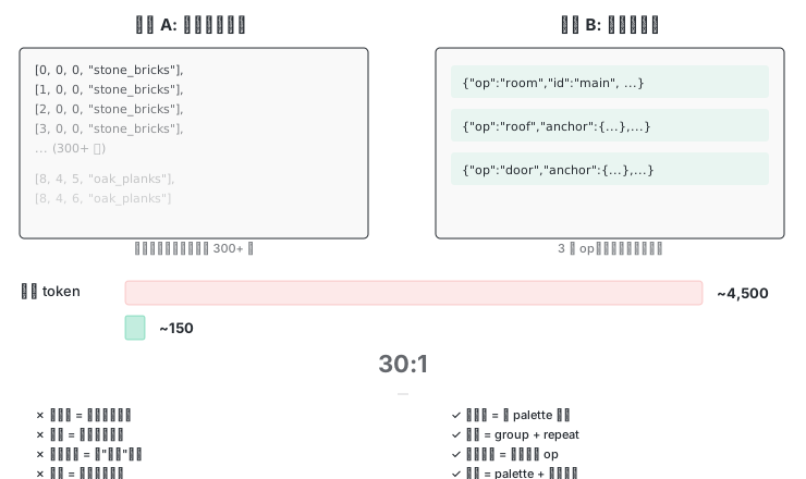
A concrete example. An 8×5×6 cottage. The coordinate approach:
[0,0,0,"stone_bricks"], [1,0,0,"stone_bricks"], [2,0,0,"stone_bricks"], ...Around 300 non-empty blocks. By mainstream BPE tokenizers, each line runs about 15 tokens, totalling roughly 4,500 output tokens.
The same building with structured instructions:
{ "op": "room", "id": "main", "box": { "from": [0,0,0], "to": [8,4,6] }, "wall_material": "wall" }
{ "op": "roof", "anchor": { "ref": "main.top_face" }, "size": [8,4,6], "shape": "gable", "material": "roof" }
{ "op": "door", "anchor": { "ref": "main.south_face", "align": "center" }, "size": [1,2,1], "facing": "south", "material": "door" }Three ops, over an order of magnitude fewer tokens than the coordinate version.
But the token gap is not the main point. Four systemic flaws matter more:
- Not editable. Want to change the roof from dark to red? The coordinate approach requires locating every roof block and replacing it. The structured approach changes one palette entry.
- Not composable. Want to reuse a row of windows? Coordinates can only be copy-pasted. The structured approach uses
group+repeat. - No incremental modification. The user says “change the roof to hip style.” Coordinates have no concept of “roof,” only scattered blocks. The structured approach replaces the roof op’s
shapeparameter; every other op stays untouched. - Not portable. When exporting to
.litematicor.mcstructure, coordinates lose all semantics. The structured approach carries palette mappings and named entities that map to any format.
These are not theoretical concerns. Early project testing confirmed that raw voxel output costs two orders of magnitude more tokens and cannot maintain spatial consistency. The ceiling for LLM-generated structured output in a single call is also limited (prior research ↗ found GPT-4 achieved only 38% completion rate). Another approach considered was Voyager ↗-style free code generation. Its visual ceiling might be higher, but the product loses named editing handles, palette reskinning, anchor alignment, deterministic testing, and the agent’s ability to do targeted revisions. CubeMuse needs editable, shareable, exportable blueprints, not disposable renders.
A JSON Instruction Set#
Why JSON#
Three reasons. LLMs natively produce structurally valid JSON, so there is no custom parser to maintain. JSON Schema provides structural validation (field types, enum values, required fields, additionalProperties: false to reject unknown fields), and a semantic validation layer on top checks that anchor refs point to existing named entities, that material roles are declared in the palette, that box.from ≤ box.to, and so on. The two layers together let the engine reject malformed ops before execution. Tool calls (tool_calls) return JSON objects directly, eliminating the step of extracting structure from free text and reducing format errors.
The Abstraction Ladder: Three Layers of Expressiveness#
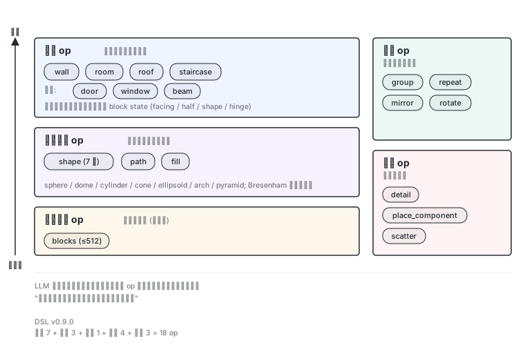
Eighteen ops are arranged into three tiers by abstraction level (this is the article’s own grouping; inside the codebase, ADR-0013 defines a separate “vocabulary three levels” by syntax complexity — shape / path / blocks — a different lens). Abstraction decreases and expressiveness increases from top to bottom. The LLM should prefer the highest tier and drop down only when necessary.
Layer 1: Structure ops. State intent, let the engine compute geometry.
This layer includes wall, room, roof, staircase, plus members like door, window, and beam. Concepts that are not standalone ops are expressed through parameters: floors and ceilings are room’s floor_material / ceiling_material parameters; a pillar is beam with its axis set to y. The model describes architectural intent. It says “put a gable roof here,” and the engine computes each block’s facing (north/south/east/west), half (top/bottom), and shape state.
Take roof as an example:
{ "op": "roof", "anchor": { "ref": "main.top_face", "offset": [0,1,0] }, "size": [10,5,8], "shape": "gable", "material": "roof" }The model wrote one line. The engine determines the ridge line position, calculates the facing for the two slopes, and fills the gable triangle (gable_fill). Overhang is not a standalone parameter; it is achieved by enlarging the roof footprint: the anchor offsets one block upward, and size adds 2 to each horizontal axis. A gable roof’s only varying state is facing (two values, one per slope); everything else is uniform across the surface.
Hip roofs best illustrate the value of structure ops. Each of the four corners needs a different corner shape (outer_left, outer_right), and facing and shape vary block by block across the entire surface. Having the model output these block states directly would produce a very high error rate. It would be handing the most error-prone part of the job to a probabilistic model.
Layer 2: Parametric geometry ops. State parameters, let the engine compute voxels.
This layer includes shape (sphere, dome, cylinder, cone, ellipsoid, arch, pyramid), path (Bresenham line voxelization, up to 64 waypoints), and fill (solid fill). These ops are not tied to architectural semantics. They are general-purpose geometric primitives. Shape supports hollow shells. A single op can produce a hollow dome. Path uses Bresenham’s algorithm for 3D polyline voxelization, useful for masts, tree branches, and cables.
Layer 3: Free voxel op. The escape hatch.
A single op: blocks, limited to 512 cells per invocation — exceeding that is a hard rejection. It directly specifies each block’s position and material. Lowest abstraction, highest expressiveness. Used for anything the upper two layers cannot express: facial features on a sculpture, trim curves, manual edit records.
“Only drop down when necessary” is not left to good intentions. The prompt pins blocks as an escape hatch (“escape hatch only — always prefer structural ops”), the schema rejects any invocation exceeding 512 cells, and evals continuously monitor the proportion of blocks in the output. All three together keep the ladder from collapsing.
Post-processing ops. These produce no new geometry; they work on existing surfaces.
detail scans the grid accumulated so far in the current scope and automatically adds decorative features like plinths, sills, and cornices. The engine auto-appends a detail op at the end of every AI-generated program, and the prompt accordingly forbids the model from manually placing such decorations. scatter randomly distributes vegetation or rubble on existing surfaces, with built-in support checks (only lands on solid surfaces, never overwrites, never floats). place_component places a prefabricated component at a specified position, functioning as a library call. These three relate to the layers above as “post-processing vs. geometry production,” not as a difference in abstraction level.
The design philosophy: what was missing was never freedom. It was the lower steps of the ladder.
Force Multipliers: Composition Ops#
Four ops that produce no geometry of their own but reuse and transform other ops’ output. They work across all layers:
- group packages a set of ops into a named component. Child ops render in an isolated sub-grid, then stamp onto the main grid. Think of it as a function definition.
- repeat translates and copies a set of ops along a vector. Three identical windows along a wall do not need to be written three times.
- mirror reflects across an x/y/z plane. State-aware: it flips facing, half, hinge, and shape chirality. Stairs face the right way after mirroring; door hinges swap sides.
- rotate rotates around the Y axis by 90°/180°/270°, also state-aware. Rotation additionally swaps
axisbetween x and z — something mirror does not do.
A symmetrical building does not need both halves described separately. One half plus mirror produces the full building and guarantees strict symmetry.
Material Role Decoupling#
The Palette maps role names to concrete blocks:
{
  "palette": {
    "primary": { "id": "minecraft:oak_planks" },
    "wall": { "id": "minecraft:stone_bricks" },
    "roof": { "id": "minecraft:dark_oak_stairs" },
    "accent": { "id": "minecraft:stripped_oak_log" },
    "glass": { "id": "minecraft:glass_pane" }
  }
}Ops reference role names ("material": "wall"), not concrete block IDs. Reskinning means changing one palette entry; every block in the building updates accordingly.
What the palette decouples is ops from block IDs, not the model from block IDs. The model still needs to know blocks: the prompt provides a block vocabulary list (wood families, stone types, stairs and slabs, glass, 16-color blocks, copper and its oxidation variants, etc.), and the model picks IDs from it to fill the palette. What the palette eliminates is repeating the same ID in every op and having to touch N places when reskinning. The prompt requires each plan to use 3 to 5 material roles with clear contrast between them.
Anchor Positioning: Keeping Doors on the Ground#
Op design solves the “what to express” problem. Another question remains: how does an op know where to go?
CubeMuse provides three positioning modes:
- Absolute coordinates
box(from/to): closed interval, suitable for the first op placed. - Anchors
anchor(ref+align+offset+inset) (preferred by the AI): reference a named op’s face, center, or edge. - Along arrays: place at regular intervals along an edge. Used for window strips, column rows, and other repeating structures.
A comparison illustrates why anchors matter.
Without anchors, the model computes door coordinates manually. The wall spans [0,0,0] to [8,4,6], so the door should be at [4,0,3]. After the wall is widened, the door is still at [4,0,3], no longer centered. After several rounds of modification, coordinates drift. Doors float in mid-air. Windows end up embedded in walls.
With anchors:
{ "op": "door", "anchor": { "ref": "main.south_face", "align": "center" }, "size": [1,2,1], "facing": "south", "material": "door" }The door attaches to the south face center of main. Move the wall, the door follows. Widen the wall, the door stays centered.
Anchors are the DSL’s fundamental guarantee: doors stay grounded, windows are evenly spaced, roofs sit flush on walls.
Under the hood, named entities (ops carrying an id) register their bounding box after execution. Subsequent ops reference them via anchor.ref: "<name>.<part>". The <part> can be a face (south_face, top_face), corner (min/max), center (center, center_bottom), floor level (floor:N), or edge (edge:<dir>). These references form a dependency graph that keeps the entire building internally consistent across multiple rounds of modification. Anchor validity is not something JSON Schema can check (Schema only knows ref is a string); it is enforced by the semantic validation layer: the ref must point to the id of a previously executed op, and the part must be a legal value.
Grid Is Truth, Op-log Is Recipe#
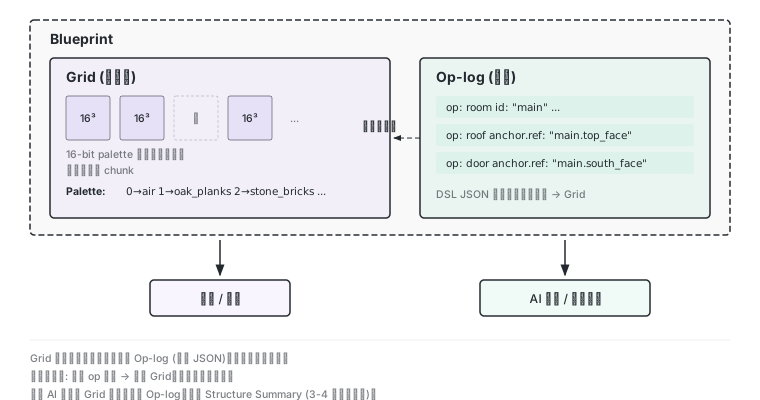
Grid: The Single Source of Truth#
The renderer reads it. The exporter reads it. Statistics read it.
- 16×16×16 chunk sparse storage; only non-empty chunks are allocated
- Each cell stores a 16-bit palette index, supporting up to 65,535 distinct blocks
- Index 0 = air
- The storage structure — palette plus index array — is shared with
.litematic,.schem, and.mcstructure; import/export adapters handle index reordering and byte-order conversion as each format requires
Op-log: Recipe, Not Result#
The Op-log is a DSL program in JSON. Execute it from its starting state, and it deterministically produces the complete Grid. The starting state is usually an empty grid, but an imported building is encoded as a starting snapshot (bounding box + palette + RLE-compressed voxels) stored in the program’s base field, with subsequent ops appended on top. Imported and generated builds follow the same path through editing, undo, AI revision, and export.
Each program carries a dsl_version field. When the engine evolves (for example, changing roof’s gable_fill default from false to true), the migration layer explicitly patches stored programs with the old default, ensuring that existing blueprints reproduce the same output block-for-block while new programs benefit from the new default. The ability to replay recipes across versions is what makes the Op-log viable as a persistent representation.
Why Both Are Needed#
Op-log only, no Grid: every render and export requires a full replay of all ops.
Grid only, no Op-log: the AI can only be fed raw voxels for modification, causing token explosion. Build history and process are lost. Semantic-level targeted modifications like replace_group become impossible.
So Blueprint = Grid + Op-log. Each serves a different audience:
Blueprint
├── Grid           ← rendering / export reads this
│   ├── Palette    ← index → block type + state
│   └── Chunks[]   ← 16³ sparse partitions
└── Op-log         ← AI comprehension / version diff reads this
└── DslProgram ← JSON, deterministic replay → GridThe Grid is not stored in the database. The database stores only the Op-log (the program JSON, including any base snapshot). Opening a blueprint replays the Op-log to produce the Grid. This guarantees the two are always consistent. Determinism guarantee: the same op sequence produces the same Grid. This is the foundation of golden tests.
One detail worth noting: what gets fed to the AI is neither the Grid nor the full Op-log, but a Structure Summary. This is a 3-to-4-line text digest containing the bounding box, top-8 material distribution, and the list of named entities. Raw voxel data never enters the LLM context directly.
Dual-Edition Export: A Version-Neutral Block Model#
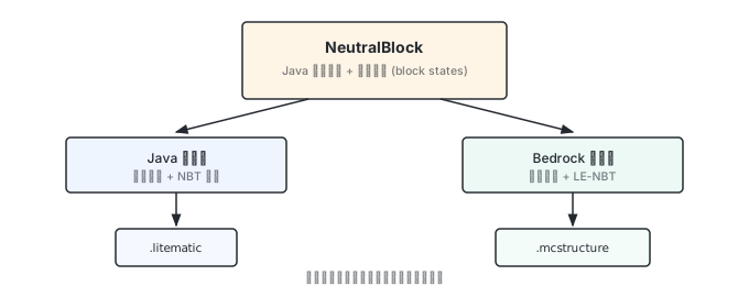
Internally, everything uses Java Edition naming plus block states as the neutral representation, called NeutralBlock. This is not a custom namespace. It reuses the Java Edition’s system because Java Edition has the most complete block name coverage and the most mature community toolchain.
At the import/export boundary, adapters handle format conversion:
- Java side:
.litematic(Litematica) import and export /.schem(Sponge v1-v3) import only - Bedrock side:
.mcstructure(Structure Block)
Cross-edition discrepancies are detected at export time, producing a substitution report. For example, Java’s quartz_pillar maps to Bedrock’s quartz_block[chisel_type=lines], tagged renamed; stair shape states (corner geometry) in Java are dropped on Bedrock (Bedrock computes corners automatically); blocks outside the vocabulary are kept as-is and tagged unsupported. The mapping table covers only blocks that the DSL vocabulary actually produces, rather than embedding a full ten-thousand-row cross-edition dataset.
Closing#
Back to the title. This system carves out four clear lines of responsibility:
- The DSL lets the model speak in intent. The engine translates intent into geometry. The model never touches block states.
- Anchors let the model reference named entities instead of computing coordinates. Structural internal consistency is guaranteed by the dependency graph.
- The Palette lets the model pick roles instead of repeating block IDs in every op. Reskinning is a one-line change.
- Dual representation gives the system both semantics and pixels: Op-log for AI and humans to read, Grid for the renderer and exporter.
This pipeline is the foundation of every subsequent design decision in CubeMuse. With it in place, the next question is: who decides which ops to call, in what order, and how many times?
References#
- 3D Building Generation in Minecraft via Large Language Models ↗, Hu et al., 2024
- Voyager: An Open-Ended Embodied Agent with Large Language Models ↗, Wang et al., 2023
- mc-bench/orchestrator ↗, GitHub